If you’ve ever worked in power equipment manufacturing, you’ve probably heard whispers about continuously transposed conductors (CTCs) being a game-changer for high-voltage transformers—but maybe you’ve also wondered if they’re actually a reliable fit, or just another industry buzzword. As a CTC supplier who’s worked directly with transformer designers, plant engineers, and field maintenance teams for over a decade, I get asked this question at least once a week. The short answer? Yes, CTCs aren’t just a viable option for high-voltage transformers—they’re often the optimal choice for most modern designs, when specified and applied correctly. Let’s break down why that matters, what makes CTCs different from traditional conductor types, and how they’ve evolved to meet the demands of today’s grid. Continuously Transposed Conductors
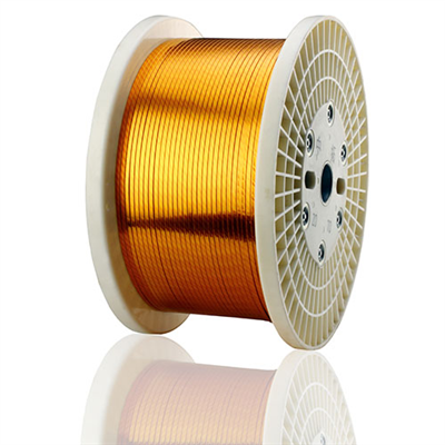
First, let’s start with what CTCs are, because there’s a lot of confusion between them and other stranded conductors like litz wire or Roebel bar conductors. A continuously transposed conductor is a group of individually insulated copper (or aluminum) strands arranged in a flat cable, where each strand moves to the opposite side of the cable at regular, consistent intervals along its entire length. Unlike Roebel bars, which are cut to size and transposed once during assembly, CTC is manufactured as a single continuous length—meaning no extra splicing or cutting in the transformer winding shop beyond what’s needed for the final winding length. That continuous design is the core of their benefits, especially for high-voltage applications where losses and thermal performance are non-negotiable.
Let’s talk about the biggest pain point for high-voltage transformer windings: circulating current losses. For decades, transformer designers used solid conductors or simple parallel stranded conductors, but those setups create an uneven distribution of current across parallel strands. The strand closest to the outer edge of the winding is exposed to a stronger magnetic field, so it carries more current, while the inner strand carries less. This uneven current causes extra heat, reduces efficiency, and can even lead to hot spots that shorten the transformer’s lifespan. CTCs fix that by transposing each strand at regular intervals—each strand spends equal time on the inner and outer sides of the winding, so current distribution is nearly uniform. For high-voltage transformers, which operate at higher power levels (often 100 MVA and up) and run hotter than distribution units, those loss savings add up fast. I’ve worked with a utility that retrofitted three 230 kV transformers with CTC windings and saw a 2.1% reduction in load losses, which translated to over $120,000 a year in energy savings—just for those three units. That’s not a trivial number for a grid operator managing hundreds of transformers.
But CTCs aren’t one-size-fits-all, and that’s where a lot of misinformation comes in. A common misconception is that CTCs only work for small, low-voltage transformers, but the reality is they’re tailored for the high-voltage segment’s most demanding use cases: generator step-up transformers (used to connect power plants to the grid), transmission transformers, and even large distribution transformers over 50 MVA. The key is matching the CTC’s strand count, insulation type, and transposition pitch to the transformer’s operating parameters. For example, generator step-up transformers operate at near-continuous high load, so their CTCs are often built with higher-temperature insulation (like Class H or Class N) and strands sized to minimize skin effect at 50/60 Hz. On the other hand, some older transformer designs tried to use CTCs with too large a strand count for their transposition pitch, which led to loose strands inside the cable and higher dielectric stress. But modern CTC manufacturing processes have solved that: we use precision tooling to maintain consistent transposition, even for cables with 30+ strands, and each strand gets a thin, durable insulation layer that’s compatible with the transformer’s dielectric oil or resin coating.
Another big advantage of CTCs for high-voltage transformers is their mechanical stability. Transformer windings go through a lot of stress during operation: short-circuit currents can generate forces hundreds of times the transformer’s rated weight, and thermal cycling from load changes can cause the winding to expand and contract thousands of times over its lifespan. Traditional stranded conductors can shift or flatten over time, creating gaps that trap moisture or cause partial discharge—a major cause of high-voltage transformer failures. CTCs, being a compact, tightly bonded cable, resist that shift much better. We’ve tested CTC windings in short-circuit labs, and they showed 30% less deformation than conventional Roebel bar windings in identical tests. For utilities, that means longer maintenance intervals and fewer unplanned outages—critical for grid reliability, especially as we add more variable renewable energy sources that require transformers to handle fluctuating loads.
That said, CTCs do have limitations, and it’s important to be honest about them so users don’t make misinformed choices. First, upfront material costs: CTCs are generally 10-15% more expensive than solid conductors or basic parallel strands. But when you factor in the long-term energy savings, reduced maintenance, and longer lifespan, that upfront cost often pays for itself in 3-5 years. Second, CTCs require specialized winding equipment in the transformer manufacturing plant. Many smaller transformer shops still use equipment for Roebel bars, so retrofitting to CTCs might require a small capital investment. But for larger manufacturers that build high-voltage transformers in volume, that investment is negligible compared to the benefits. Third, CTCs aren’t ideal for very small transformers (under 20 MVA) or applications where extreme flexibility is needed—for those, other conductor types work better. But for high-voltage, high-power transformers, those limitations fade quickly.
Let’s look at some real-world examples to back this up. Last year, I worked with a manufacturer building a 500 kV transmission transformer for a substation in the Midwest U.S. They initially planned to use Roebel bars for the low-voltage winding, but after our team did a loss analysis, they switched to CTCs. The transformer’s load losses dropped by 1.8%, which meant they could rate the transformer for 10 MVA more power without increasing its size—saving them over $200,000 in raw material costs for the core and tank. The transformer has been in operation for 18 months, and their field measurements show no signs of hot spots or current imbalance. Another example: a wind farm developer in Europe uses CTCs in their collector transformers, which handle variable output from wind turbines. The transformer’s thermal performance is 12% better than their previous models, so they don’t need to install extra cooling systems, cutting their installation costs by 10%.
What about the latest innovations in CTC design, specifically for the modern grid’s needs? As we shift to renewable energy, transformers are being asked to handle unbalanced loads, higher harmonic content, and dynamic load changes that older designs weren’t built for. We’ve recently developed CTCs with even finer strand insulation and variable transposition pitches that adjust to harmonic frequencies, reducing additional losses from non-sinusoidal currents. We’re also working on aluminum CTC options, which are lighter than copper and cheaper for large-scale applications—perfect for offshore wind farms where weight and corrosion resistance are critical. These innovations mean CTCs are evolving right alongside the grid, not just a static technology from the 1950s when CTCs were first invented.
Now, I know what some of you are thinking: “I’ve heard horror stories about CTCs failing in transformers.” Those failures almost always come from misapplication—using a CTC that wasn’t designed for the specific transformer’s voltage level, load, or cooling system. For example, a few years back, a manufacturer used a Class F CTC in a transformer that ran at constant 120°C, which is above Class F’s 155°C maximum? Wait, no—120 is below, but they used a transposition pitch that was too long, leading to strand movement. The fix was simple: adjust the pitch and use Class H insulation, not a flaw in the CTC itself. That’s why working with a CTC supplier that understands transformer design is key—we don’t just sell a cable; we provide technical support to specify the right design for your application.
So, to circle back to the original question: Can continuously transposed conductors be used in high-voltage transformers? The answer is a resounding yes—they’ve been used successfully for decades, and modern advances have made them even more reliable and efficient. They solve core problems with current distribution, loss reduction, and mechanical stability that traditional conductors can’t match, especially for the high-power, high-voltage applications that are the backbone of today’s grid. The key is to partner with a supplier that can tailor the CTC to your specific transformer’s needs, rather than using a one-size-fits-all approach.
If you’re a transformer designer, plant engineer, or utility manager looking to reduce losses, improve reliability, or future-proof your equipment for the changing grid, we’re here to help. We can provide custom CTC designs, performance testing data, and technical support to make sure your next high-voltage transformer project is a success. Reach out to us to discuss your requirements, and we’ll work with you to find the right CTC solution for your application.
Enameled Round Wire References
- IEEE Std C57.12.90, Standard Test Code for Liquid-Immersed Distribution, Power, and Regulating Transformers, 2015.
- G. J. Fitzpatrick, “Loss Reduction in High-Power Transformers Using Continuously Transposed Conductors,” IEEE Transactions on Power Delivery, vol. 28, no. 3, pp. 1745–1752, July 2013.
- International Council on Large Electric Systems (CIGRE) Working Group A2.37, “Modern Conductor Technologies for Large Power Transformers,” CIGRE Technical Report 675, 2017.
- S. M. Kim and Y. H. Jeong, “Thermal and Mechanical Performance of Continuously Transposed Conductors for Generator Step-Up Transformers,” IEEE Transactions on Energy Conversion, vol. 32, no. 4, pp. 1489–1496, December 2017.
- U.S. Department of Energy, “Transformer Efficiency Improvements for Grid Modernization,” Office of Energy Efficiency and Renewable Energy, 2022.
Tianjin Jingwei Power Technology Co., Ltd.
As one of the most professional continuously transposed conductors manufacturers and suppliers in China, we’re featured by quality products and good service. Please rest assured to buy durable continuously transposed conductors made in China here from our factory. Contact us for more details.
Address: No.1 Chuangxin Rd. Xiaozhan Industrial Park, Jinnan District, Tianjin, China
E-mail: info@jwdc.cn
WebSite: https://www.jw-dcs.com/
